


All Products
-
Cylindrical Roller Bearings
-
Spherical Roller Bearings
-
Rolling Mill Bearings
-
Excavator Bearings
-
Angular Contact Ball Bearings
-
Deep Groove Ball Bearings
-
Split Bearings
-
Plummer Block Housings
-
Taper Roller Bearings
-
Ball Screw Support Bearings
-
Automobile Bearings
-
Spherical Plain&Rod End Bearings
-
CARB Bearings
-
Needle Roller Bearings
-
Thrust Taper&Spherical Roller Bearings
-
Concrete Mixer Truck Bearings
-
3200&3300 double row angular contact ball bearings
-
Self-aligning Ball Bearings
-
Cylindrical roller bearings for oilfield
-
Double row cylindrical roller bearings
-
Brand Bearings
-
Mud pump bearings
-
Insocoat Bearings
-
Track Rollers
Contact Person :
Bruce
WhatsApp :
+(86)18864882435
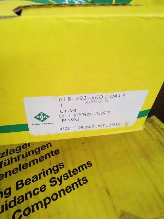
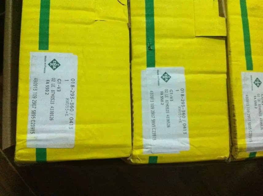
INA carriages RWU55-E-G1-V3


| Place of Origin | France |
|---|---|
| Brand Name | INA |
| Model Number | RWU55-E-G1-V3 |
| Minimum Order Quantity | 1 set |
| Price | ASK |
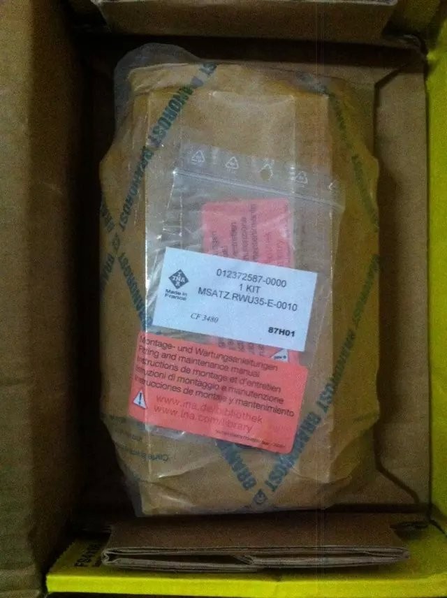
| Packaging Details | Original |
| Delivery Time | 3 days for stocks; |
| Payment Terms | T/T;Western union;paypal |
Product Details
Product Description
INA Carriages RWU55-E
--- standard carriage with full complement recirculating roller system for linear recirculating roller bearing and guideway assembly, for oil or grease lubrication
![]()
![]()
INA RWU55-E-G1-V3 specifications:
| H | 70 mm | ||
| B | 140 mm | ||
| L | 172,7 mm | Minimum covered length for sealing the lubrication connections | |
| 1) | Locating face | ||
| 2) | Marking | ||
| 5) | Fixing screw | ||
| A1 | 43,5 mm | ||
| A3 | 8,1 mm | ||
| A4 | 8,1 mm | ||
| aL max | 47 mm | a L and a R are dependent on the length l max of the guideway | |
| aL min | 20 mm | a L and a R are dependent on the length l max of the guideway | |
| aR max | 47 mm | a L and a R are dependent on the length l max of the guideway | |
| aR min | 20 mm | a L and a R are dependent on the length l max of the guideway | |
| b | 53 mm | Tolerance: -0,005 / -0,035 | |
| G2 | M14 | For screws to DIN ISO 4762-12.9 | |
| Max. tightening torque [MA] in Nm: | |||
| M6 = 10 | |||
| M8 = 24 | |||
| M10 = 41 | |||
| M12 = 83 | |||
| M14 = 140 | |||
| M16 = 220 | |||
| M20 = 470 | |||
| GS | M4x4 | DIN EN ISO 4027 | |
| H1 | 11 mm | ||
| H4 | 32 mm | ||
| H5 | 12 mm | ||
| h | 45 mm | ||
| h1 | 22,5 mm | Tolerance: +/-0,5 | |
| JB | 116 mm | ||
| JL | 95 mm | ||
| JL5 | 21,6 mm | Position of lubrication hole in adjacent construction. | |
| JL6 | 32,9 mm | ||
| JLZ | 70 mm | ||
| jL | 60 mm | ||
| K1 | M14 | For screws to DIN ISO 4762-12.9 | |
| Max. tightening torque [MA] in Nm: | |||
| M6 = 17 | |||
| M8 = 41 | |||
| M12 = 140 | |||
| M14 = 220 | |||
| M16 = 340 | |||
| M24 = 1100 | |||
| K3 | M12 | For screws to DIN ISO 4762-12.9 | |
| Max. tightening torque [MA] in Nm: | |||
| M5 = 10 | |||
| M6 = 17 | |||
| M8 = 41 | |||
| M10 = 83 | |||
| M12 = 140 | |||
| M14 = 220 | |||
| M16 = 340 | |||
| K6 | M12 | For screws to DIN ISO 7984-8.8 | |
| Max. tightening torque [MA] in Nm: | |||
| M6 = 10 | |||
| M8 = 24 | |||
| M10 = 48 | |||
| M12 = 83 | |||
| M14 = 130 | |||
| M16 = 220 | |||
| L1 | 127 mm | ||
| LS | 2,75 mm | ||
| lmax | 2520 mm | Maximum length of single-piece guideways; longer guideways are supplied in several sections and are marked accordingly. | |
| Maximum single-piece guideway length of 6 m by agreement. | |||
| N2 | 6 mm | Maximum diameter of lubrication hole in adjacent construction | |
| N3 | M6 | Maximum screw depth 6 mm | |
| N4 | M6 | ||
| O | 10x1,5 mm | DIN 3771 | |
| T5 | 18 mm | ||
| T6 | 14,8 mm | ||
| W10 | 10 mm | Width across flats | |
| W7 | 7 mm | Width across flats | |
| W8 | 8 mm | Width across flats | |
| mW | 5,24 kg | Mass of carriage | |
| mS | 13,1 kg/m | Mass of guideway | |
| C | 136000 N | Basic dynamic load rating | |
| C0 | 320000 N | Basic static load rating | |
| M0x | 3287 Nm | Static moment rating about X axis | |
| M0y | 7404 Nm | Static moment rating about Y axis | |
| M0z | 6667 Nm | Static moment rating about Z axis | |
Recommended Products